Background: Facial asymmetries come in an almost endless variety of bone and soft tissue compositions. Many are congenital/developmental in origin and some are iatrogenic. (caused by surgery or trauma) Evaluation of facial asymmetries is done through a combination of physical, pictorial and 3D CT scanning.
While not a big surface area of the face, orbital asymmetries are often the most complex. The orbit is the only structure on the face that has four bony sides, contains a conical volumetric space, has a very important organ that lies within and is covered by moveable musculocutaneous ‘flaps’. While there are a lot of structures that encompass the orbit, many asymmetries are reflected by the position of the eyeball that lies within. With an opposite eye for comparison even subtle differences in the position of the eyes can be discerned.
A critical assessment question is to determine in orbital asymmetries in which the eye positions are different as to the anatomic cause. The easiest structures to evaluate is the bone. The periorbital skeletal structures are best evaluated with a high resolution 3D CT scan which can clearly show the differences n the level of the orbital floors and the circumferential orbital rims.
Case Study: This middle-aged male presented with a complex history to his right orbital asymmetry. He had an initial surgery of orbital decompressions, subsequent asymmetries and multiples surgeries to address it with layers of implants on the infraorbital rim and orbital floor. Despite these efforts the right eyeball remained lower and back than that of the left and the entire orbital ‘box’ and cheek were lower and recessed.
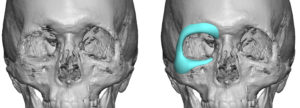
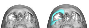
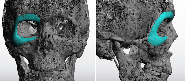
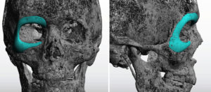
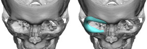 A 3D CT scan was done and augmentation of the right orbit was designed by mirror imaging the desired left side and overlaying on the right. This creates a horseshoe-shaped orbital rim implant that was near circumferential in coverage. The thinner of the orbital floor and prior surgeries did not permit a precise assessment of their levels.
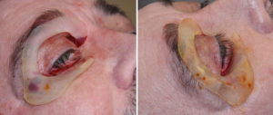
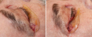
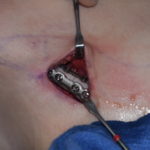
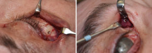 Under general anesthesia a lower blepharoplasty incision (reopening old scar) exposed the infraorbital rim, orbital floor and lateral orbital rim up past the fronto-zygomatic suture. Subperiosteal dissection continued blindly aided by the opposite hand across the brow bone to the medial orbit. A small medial upper blepharoplasty incision was done to complete the extent of medial brow bone dissection. The implant was then threaded through the two incisions, positioned and secured with 4 microscrews. A small orbital floor implant was fashioned from a 3mm ePTFE block and placed behind the prior work done on the anterior orbital floor. Closure required a cheeklift/suspension and lateral canthoplasty.
 This case illustrates that trying to ‘eyeball’ orbital asymmetries is fraught with inaccuracies and leads to suboptimal surgeries and multiple subsequent revisions. While 3D CT planning and implant design, if desired, is not a guarantee of a perfect outcome in orbital asymmetries, one can at least walk into surgery with an increased level of confidence about the proposed surgery.
Case Highlights:
1) The complex dimensional needs of most orbital asymmetries is best treatment planned by 3D CT scans and computer assessment.
2) Orbital asymmetries are often near circumferential and are most ideally planned by a custom orbital implant design.
3) The surgical placement of a custom orbital rim implant can be inserted through a lower eyelid incision combined with a small upper eyelid incision.
Dr. Barry Eppley
Indianapolis, Indiana