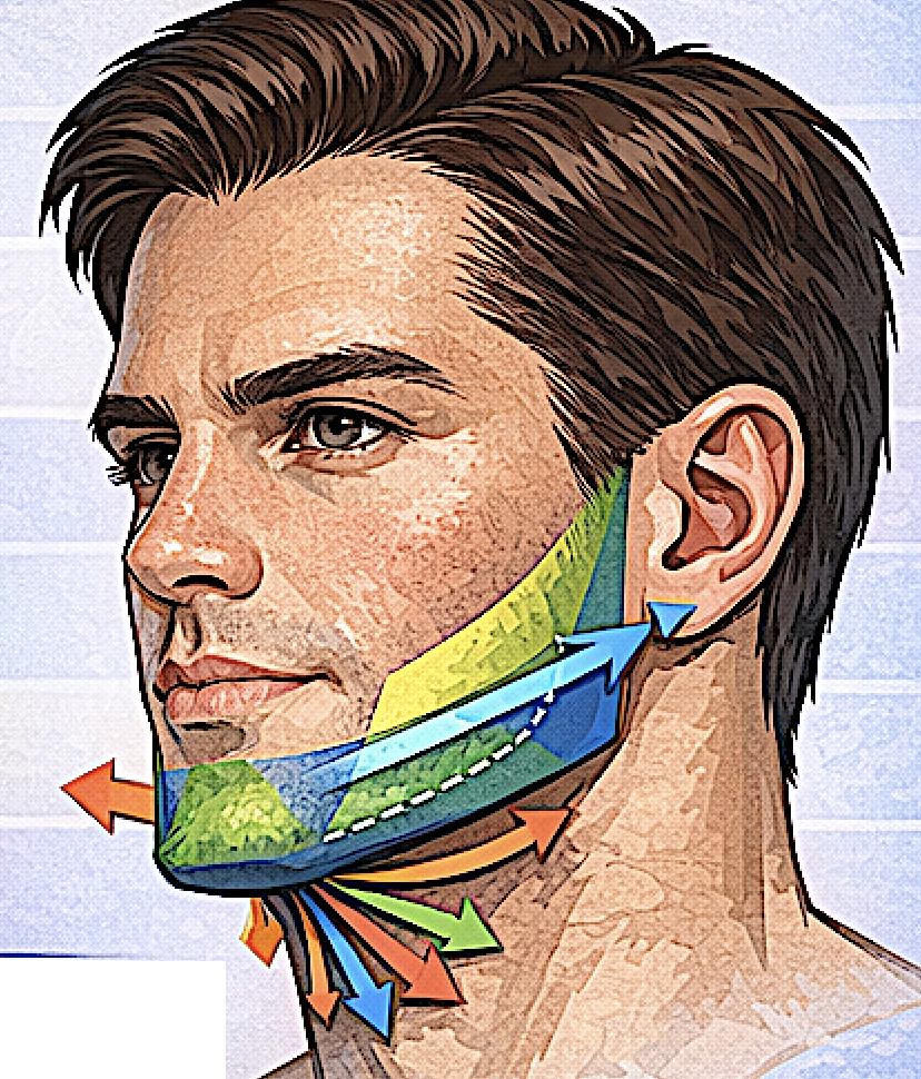
In advanced CAD planning for total jawline implants, I analyze the lower face using five aesthetic vectors.These vectors describe the direction and magnitude of skeletal augmentation needed to produce a strong, natural male jawline. Instead of thinking in millimeters alone, it is also useful to think in directional growth patterns.
Below are the five vectors used in high-end jawline implant design.
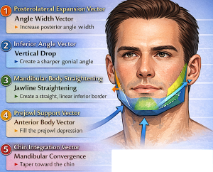
1. Posterolateral Expansion Vector
(Angle width vector)
Direction:
Posterior + Lateral
Purpose:
Increase gonial angle width.
Typical CAD adjustment:
+6 mm to +12 mm
Effect on appearance:
- stronger masculine frame
- wider posterior mandible
- improved jaw-to-cheek balance
Key design rule:
Most width should occur behind the masseter muscle midpoint, not along the anterior edge of the muscle.
2. Inferior Angle Vector
(Vertical jaw angle drop)
Direction:
Downward
Purpose:
Create a sharper gonial angle and stronger inferior border.
Typical range:
O mm to +6 mm inferior drop
Visual effects:
- sharper jaw angle
- more defined lower border
- stronger profile
Too much vertical drop can create a heavy lower face, so this vector must remain subtle. Many patients think they need more than they do.
3. Mandibular Body Straightening Vector
(Inferior border vector)
Direction:
Posterior to anterior along the inferior border
Purpose:
Create a straight continuous jawline from angle to chin.
Common problem corrected:
Angle strong
Body concave
Prejowl hollow
Typical CAD augmentation:
2–5 mm lateral
0–3 mm inferior
Visual effect:
A clean model-like jawline line.
4. Prejowl Support Vector
(Anterior body vector)
Direction:
Anterior + Lateral
Purpose:
Fill the prejowl depression.
Typical augmentation:
+2–4 mm
Effect:
- eliminates jawline dip
- improves chin-jaw transition
- reduces early jowl appearance
This vector is subtle but critical for jawline continuity.
5. Chin Integration Vector
(Mandibular convergence vector)
Direction:
Medial convergence toward the chin
Purpose:
Ensure the jawline tapers naturally into the chin.
Typical CAD adjustments:
0–2 mm lateral
Effect:
- prevents square anterior jaw
- maintains masculine but natural chin
If this vector is ignored, implants produce the “boxy jaw” look.
Combined Vector Map
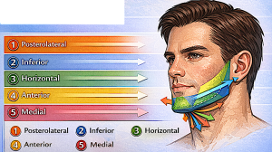
When all five vectors are applied simultaneously, the implant produces a balanced 3D mandibular expansion.
Vector summary:
|
Vector |
Direction |
Function |
|
1 |
Posterolateral |
Angle width |
|
2 |
Inferior |
Angle drop |
|
3 |
Horizontal |
Jawline straightening |
|
4 |
Anterior |
Prejowl support |
|
5 |
Medial taper |
Chin integration |
Why vector-based design works
Traditional implant planning often uses uniform thickness values.
Vector-based design allows:
• natural skeletal growth simulation
• better facial harmony
• smoother contour transitions
• improved symmetry correction
This approach is one reason modern custom jaw implants look far more natural than older type implant designs.
Dr. Barry Eppley
Plastic Surgeon